Uncategorised
3Dprinter
Autocad
Autodesk
Bill of material
Bin vent
Bridge designer
Cad career
Cad design
Calculate carbon footprint
Collection
Design services
Drafting
Drafting job
Drawing number
Dust collector
Environmentally freindly design
Handrail
Hydraulic valve
Industrial air
Lean manufacturing
Log splitter
MRP
Material recovery facilities
Methane digester
Municipal projects
New product invention
OSHA ladder
PDM
Part numbering
Project management
Project management tools used in design and manufacturing
Projects
Railroad crossing
Safety regulation
Solidworks
Sred
Stair design
Sustainability
Track design
Ventilation
Waste reduction plan
Wastewater clarifier
AAA Drafting Services AutoCad and SolidWorks CAD drafting services
SR&ED or SRED, Canadas's R&D program for manufacturers
SRED
SRED, is an abbreviation for Scientific Research and Experimental Development expenditures claim. It is a service provided by the Canadian Government to allow Canadian inventors / manufacturers to reduce their current or future taxes by deducting current and capital expenditures. The SRED program allows Tax deductions and/or Income Tax credits in the form of a cash refund or a reduction of taxes, or a combination of the two.
Completing a SRED Claim
To complete a SRED claim, form T661 has to be filled out with additional supporting documents dictated by the type of claim and business structure. Since Revenue Canada first uses the forms information to determine eligibility, the form should be completed by a technical expert who has great familiarity with the project. The expert could be the person who developed the process or an outside expert. The form also requires extensive reporting of expenditures related to SRED which should be handled by an accounting professional.
Getting Started
What follows is a description of the information required for making a SRED application using the form
General Information
In this section, basic information about you and your business is collected. This includes name, tax year, business identification, partnership information, number of projects and the names of those responsible for those projects.
Project Information
The project information section is filled out by someone intimately familiar with the technical aspects of the project. There are precise guidelines about what must be explained and the manner in which it must be explained. The project information is broken down into five parts as follows.
Part A - Project definition and identification, project title, start date, completion date and field of science. Details are included if this is a previous sred project, if it is a joint work or collaboration and the location description and purpose of the SRED work
Part B - Goes into how the project advances existing scientific knowledge. It discusses experimental development, objectives of the technological advancement, what advancements were you trying to achieve, what technical obstacles had to be overcome as well as work that was performed in the tax year to overcome technological obstacles.
Part C - Details the basic or applied research that was performed and what scientific knowledge was advanced. There is a summary and explaination of how the work that was performed in the tax year advanced scientific knowledge.
Part D - This section outlines who prepared the technical descriptions, the key employees, what SRED work was performed out of canada or carried out by others
Part E - Goes into general project costs including materials, subcontracting, salary, wages and overhead related to SRED work
Calculation of expenditures
The SRED application process allows for expenditures to be deducted in two basic ways. You can offset SRED expenses against income for the fiscal year the expenses were incurred. Or you can use the PPA or Prescribed Proxy Amount method where the PPA amount is used to create an income tax credit. Your accountant can help you decide which is the best route to take for your particular company structure.
Part A - This section is where the calculation method is selected, Traditional and (PPA) Prescribed Proxy Method. Once chosen, the selection cannot be changed.
Part B - Here is where there is a full accounting of allowable expenditures, salary & wages directly engaged, specified and other than specified employee wages, both inside and outside canada, treatment of unpaid salaries and wages, cost of materials consumed and transformed, sred contracts, sred equipment lease costs, overhead and other expenditures, third party payments , capital expenditures.
Part C - This summary section is for the calculation of the pool of deductible SRED expenditures, less federal and provincial government assistance, state other and non governmental assistance, ITC's and sales of capital assets.
Calculation of expenditures for Input Tax Credits (ITC's)
Part A - This section details out prior years unpaid amounts, PPA, expenditures on shared use equipment, qualified expenditures transferred to you and government assistance provided.
Calculation of PPA
Part A - This summary section details out the total PPA available for ITC use.
Project Management Plan - Bascule Bridge Repair
Project management plan - Bascule Bridge Repair. The challenge was to replace the main lift bridge gearbox in a 30 year old bascule bridge. The gearbox manufacturer had long since gone out of business so a custom gearbox had to be built using the original gearbox specifications and noting the special mounting conditions of the existing gearbox.
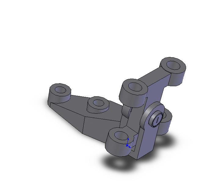
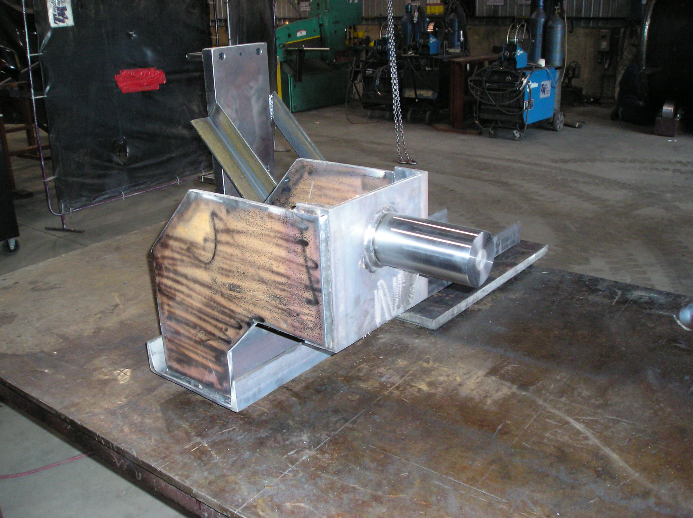
One important part of the plan was the fabrication of a special alignment jig. The alignment jig was used in place of the new gearbox, to make sure the new gearbox base was installed exactly in the right position. The alignment jig also allowed some leeway in the delivery of the new gearbox. The new gearbox could be received while the work was proceding on the installation of the new base.
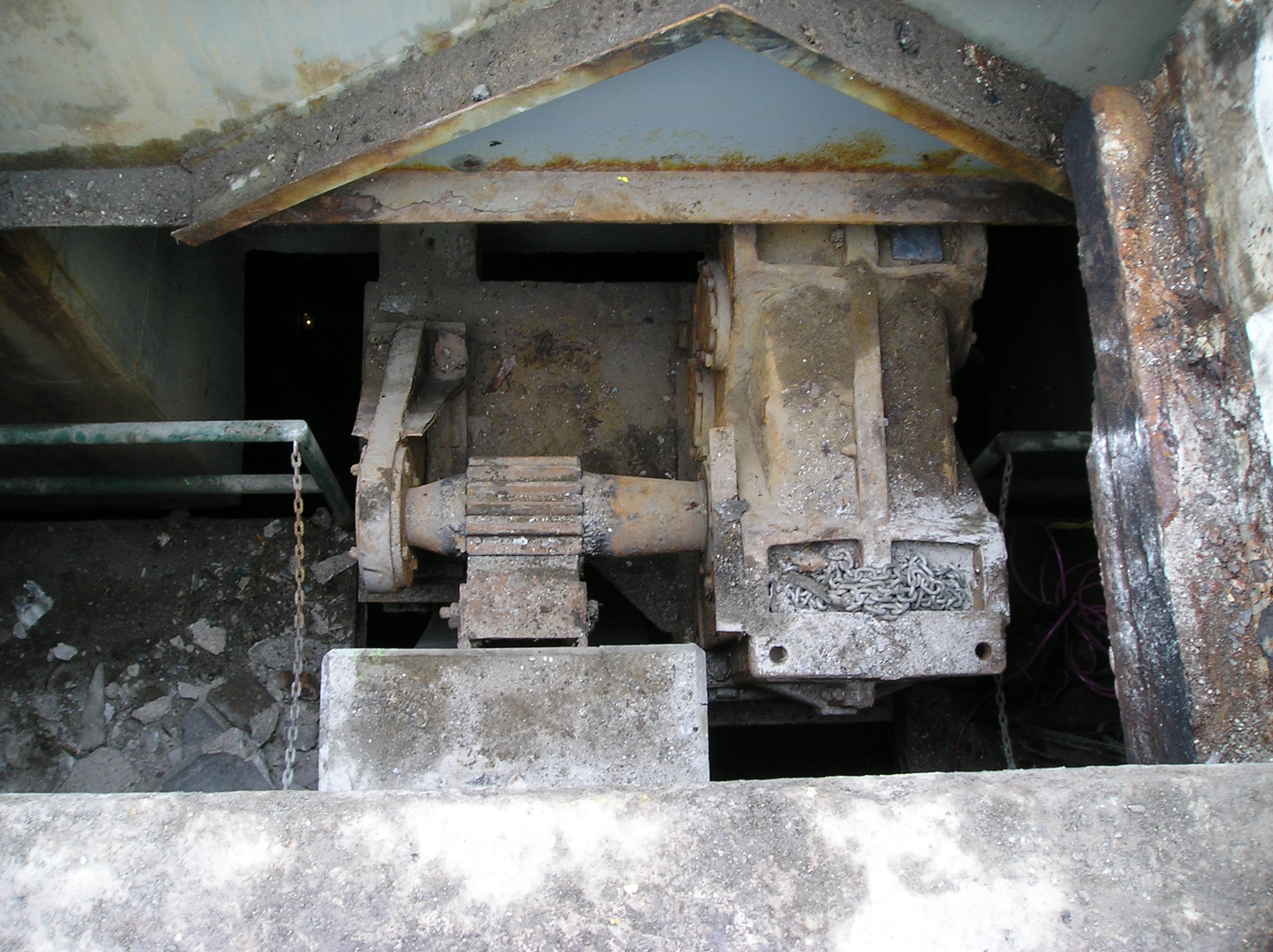
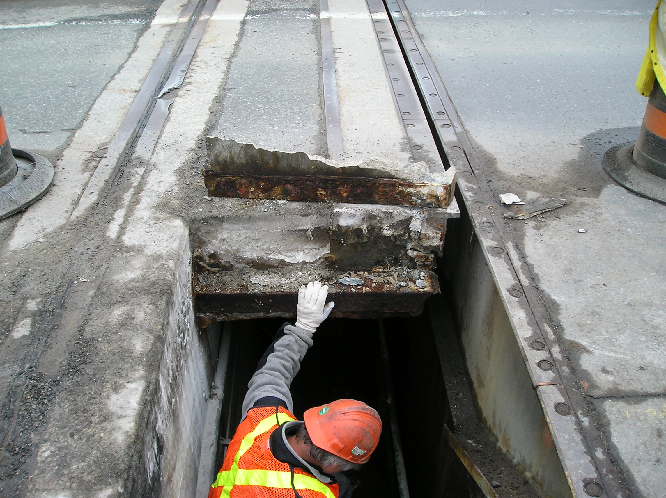
A concrete plug was removed to expose the old gearbox, pinion and bearing. The rusted condition of the old gearbox mount could well have impacted on the bridges safety in future years. Once the plug was removed, plans could be implemented to finally remove the old components from the bridge. It was determined the pinion would have to be cutoff the gearbox, in order to lift the gearbox through the opening.
The concrete plug presented some challenges on removal when one side broke off. A new concrete plug had to be fabricated quickly while the open hold was covered with a thicj steel plate. The steel plat allowed traffic to to pass while final alignment of the new gearbox was taking place. Note: 20 ton trucks crossing the bridge dont make life easy when aligning gearboxes !
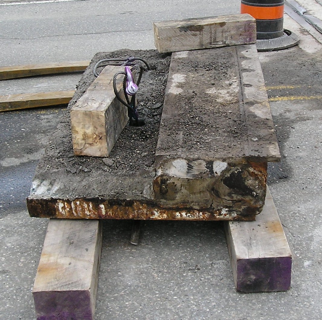
The access hole with the concrete plug removed. One key element of the project management plan was using a contractor with extensive experience in bridges and roadwork. Not all problems can be foreseen, but if you get the project 95% planned out ,a good team can push it to 100%, working through unforeseen problems.
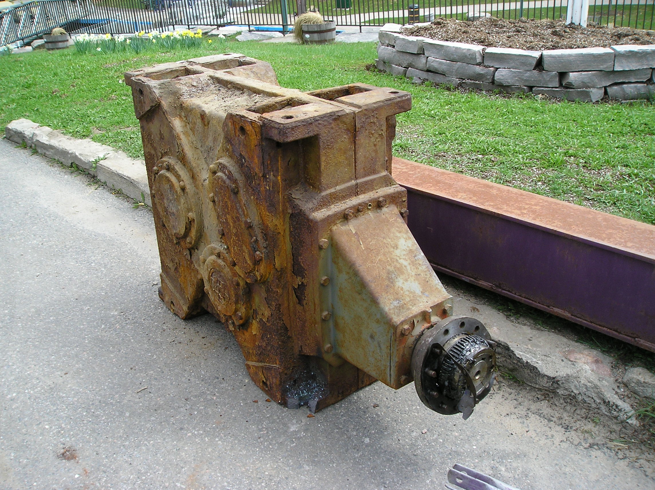
The old gearbox after removal, note the condition due to years of road salt dropping down from the bridge deck.
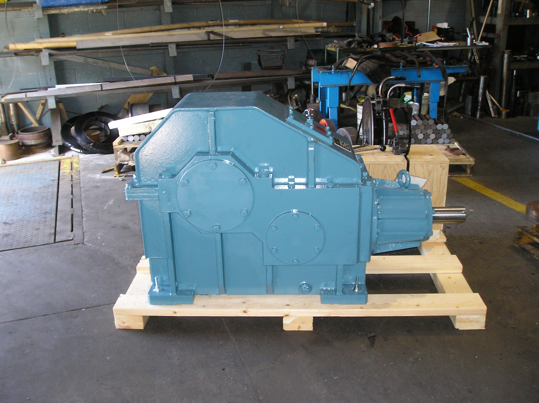
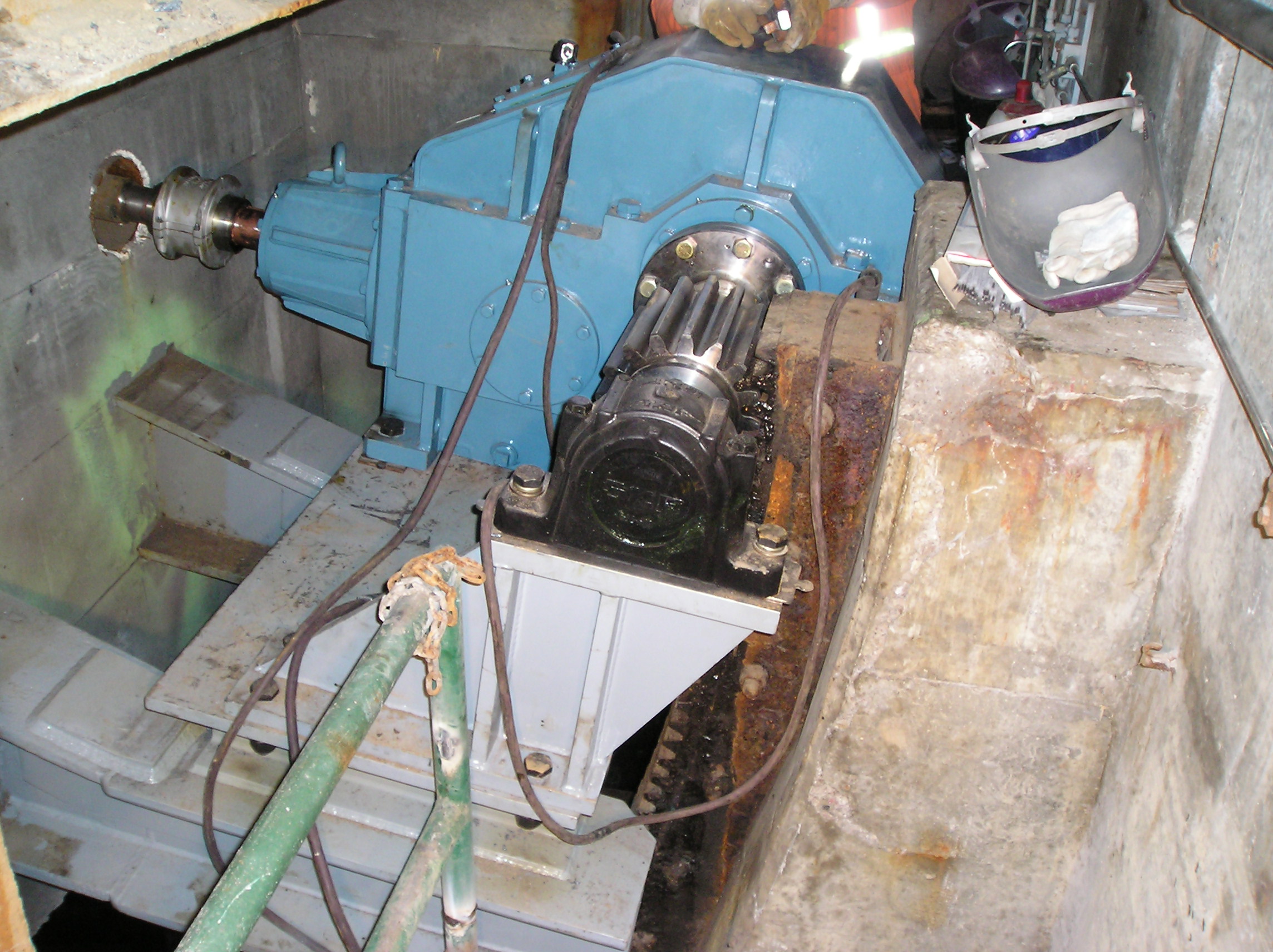
The new gearbox installed with new mounting brackets, pinion, bearing and coupling. A new stainless steel cover was later instlled to deflect road salt from the bridge deck. The work was completed in time for the summer boating season to begin and the bridge opeed without problems.
Part numbering and PDM systems
Part numbering back in the days of paper drawings, involved part numbers on various drawings. Very often this part number corresponded to a drawing number. To find everything you needed to know you simply looked up the drawing. It was possible that many drawings could be made with different part numbers showing the same part. The more designers there were making drawings, the more the possibility for duplicate parts with different numbers. Only a diligent engineering record keeper with a thorough knowledge of all the drawings could prevent this.
Nowadays we have 3D modeling systems that create separate files for the assembly and part and separate files for the drawing. They can and often do have the same part number. Now an army of diligent people are required to prevent same parts with different part numbers. Most 3d modeling systems let you name the parts, assemblies and drawings anything you want. So it's possible that similar parts can have wildly varying filenames only based on who created the file.
The need for proper document management is more acute than it ever was before. For manufacturing companies to remain competitive parts and assemblies need to be standardized and reused wherever possible. Even where the products are so called "one-of's" there is often room to standardize. Look at automotive assembly tooling and fixturing. At one point every fixture was "unique". The advent of standardized "NAAMS" tooling has allowed designers to reuse many components over and over again keeping the number of special parts to a minimum.
All manufacturing companies can benefit from this type of standardization. There are always parts that are used over and over again such as mounting brackets, limit switch mounts, drive housings, roller bearing mounts and so on. Much can even be accomplished even with only with a good stock of shims and nutplates in the engineering library. These items can easily be dragged and dropped into any assembly from a central part library.
PDM Systems
Production Data Management systems exist and are good at preventing different parts from having the same number. They also help with revision control making sure everybody only uses the latest revision of a part. They cannot always prevent new parts being uploaded to the drawing vault that are identical to existing parts but with different part numbers. They do work well with central drawing libraries of often reused parts.
The same old dilligent, detail oriented individual with a thorough knowledge of the entire engineering database is still a necessity. Now that person will likely have a PDM system at his or her command but so long as its done properly and used by the book, it should not matter if they use PDM, Excel, a Database, or an MRP system or a 3 ring binder.
Structured Bill of Material
Perhaps the most potent weapon that dilligent person needs to have is a structured bill of material in their arsenal. The structured bill is a single document that all designers use to create new projects. It simply summarizes what old assemblies are available for reuse so that duplication of part numbers and assemblies is kept to a minimum.
When a designer chooses a new part number for a new assembly, the old part numbers are there for review so that the designer can add new configurations to them, or modify them, or create something totally new.
The structured bill is not at all a fancy document. In its simplest form it could be just a word document. It adapts to changes in the engineering department by serving as a record for decsions to standardize on certain frames and assemblies and purchased parts. It can easily be added to and expanded and regularly distributed in its latest revision to all designers and draftsmen in the department.
MRP Systems
The MRP system holds out the best promise to assist the dilligent person because most MRP systems have sophisticated "where used" functions that allow you to search across multiple projects to find parts, or drawings that are used in multiple locations.
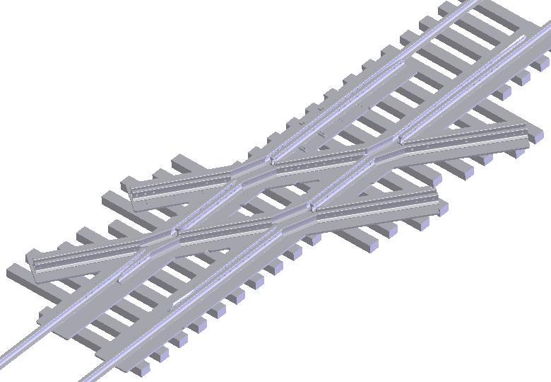
Diamond Crossing

Duct Layout