|
|
 |
 |
 |
||
|
Common Engineering ScalesMost CAD systems allow the user to draw at whatever scale he or she feels like. However, if fabrication shops are going to be using your drawings you will help them more by drawing views to commonly accepted engineering and architectural scales. Many shops like to keep drawings to a consistent scale so fabricators get used to knowing how drawings are laid out. This is just as important in plant layout and architectural drawings where 1/8"=1'-0" and 1/4"=1'-0" are standards for construction and building permit work. In machine design 3"=1'-0" and 1-1/2"=1'-0" are very commonly used. Drawing to scale is important since the CAD system can make scale templates more accurately than ever before. Drawings can be plotted at full scale and parts can be checked against them simply by placing them on the drawing. Paper plots can be glued to wooden forms and templates can be sawn to shape with minimal layout time. The following table shows typical engineering scales and useful data to help set up your sheet layout. You can use this chart in many different ways. Most often you would be starting off with an autocad file that was drawn full size in model space and now needs to have a drawing border to a specific drawing scale placed around it.
|
||||||||||||||||||||||||||||||||||||||||||||||||||
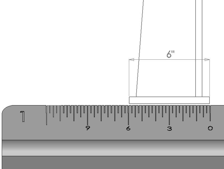
How to Scale a drawing to make sure it is accurate |
||||||||||||||||||||||||||||||||||||||||||||||||||
|
||||||||||||||||||||||||||||||||||||||||||||||||||
|
||||||||||||||||||||||||||||||||||||||||||||||||||
|
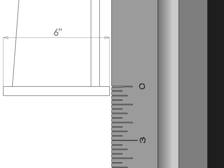
Simply draw your drawing border actual size and scale it up using the reciprocal numbers untill your object fits nicely within the drawing border. Under drawing scale in the title block, label the scale from the chart whose reciprocal created the best fitting border Also if you have a drawing border that is 3/4"=1'-0" and you want to make it 1/2"=1'-0", look up the reciprocals for both scales. Since you are making your drawing border smaller in this case you need to divide 16/24 = .6666667. Scale the original border down by this amount and your scale is changed. The Ratio and Decimal numbers can be helpful if you are working in paper space and need to know what the scale factors are for window resizing in order to create the proper scale. Purchasing an engineering scale or an architectural scales is important should you need to measure off drawings in order to verify that they have been made properly to scale. Additional drawing related information can be found here: How to convert an Autocad drawing to a Solidworks drawing |
||||||||||||||||||||||||||||||||||||||||||||||||||