Industrial drafting
Methane Digester & Industrial Mixer choices
Methane digesters have traditionally been used in waste water treatment plants to break down sludge into a more environmentally freindly material for disposal. More frequently they are being used by farmers and ranchers to create biogas from organic waste produced by cattle and swine herds.
In any digester, properly mixing the sludge is an essential factor in sludge breakdown and gas production. Efficient mixing ensures effective digester operation and greatly speeds up the biogas creation processes by doing the following:
- 1. Utilizing as much of the total volume of the methane digester as possible.
- 2. Quickly distributing the raw sludge throughout the digester to put the microorganisms in contact with fresh food sources as quickly as possible.
- 3. Achieve good pH control by distributing buffering alkalinity throughout the digestion tank.
- 4. Obtain the best possible distribution of heat throughout the tank.
- 5. Minimize the deposition of grit and inert solids on the bottom or float scum material to the top.
Mixing can be accomplished by various means using:
- Mechanical mixers
- Digester gas recirculation
- In-Line mixers
Mechanical Mixing in Sludge Digesters
Mechanical mixers are found mainly on fixed-cover digesters. Normally, one, two or three of these units are supported on the roof of the tank. Explosion proof motors drive the mixers. They can be traditional propeller styles or more advanced reciprocating in line mixers.
A key advantage to reciprocating type in line mechanical mixers is the reduction in the size of the drive motor and hence reduction in the amount of energy required to mix the sludge. Typically propeller style mixers in a large digester tank may require 60 horsepower motors or greater. Reciprocating mixers provide proper mixing with 10 to 15 horsepower motors.
The mixer agitator shaft extends down through draft tubes. The draft tubes are 304 stainless steel and range from 18 to 24 inches in diameter. The draft tube ends 18 inches below the normal liquid level in the tank.
The bottom of the draft tube is straight when reciprocating mixers are used. When propeller type mixers are used the draft tube can have a 90 degree elbow. The 90-degree elbow type is placed so that the discharge is along the outside wall of the tank to create a whirlpool action.
The mixer agitator is located about two feet below the top of the draft tube. This type of unit usually has a reversible motor so that the propeller may be rotated in either direction. In one direction the contents are pulled from the top of the digester and forced down the draft tube to be discharged at the bottom. By operating the motor in the opposite direction, the digested sludge is pulled from the bottom of the tank and is then discharged over the top of the draft tube near the surface.
With a reciprocating style mixture no reversal is necessary due to more efficient mixing action
Propeller mixers are sometimes subject to shaft bearing failure due to the abrasiveness of the sludge, and corrosion by hydrogen sulphide present in the digester gas. Maintenance consists of lubrication of bearings and adjustment of drive belts if used.
Sludge recirculation pumps are sometimes used to mix digesters. This method is common in smaller tanks, when external heat exchangers are utilized, a larqer centrifugal pump is used to recirculate the sludge and discharge it back into the digester through one or two directional nozzles at the rate of about 200 to 1000 gpm. (900-4550 litres per minute)
Maintenance of the recirculating sludge pump requires normal lubrication and a good pump-shaft water sealing system. The digested sludge is abrasive and pump packing, shaft, wearing rings, and impellers are rapidly worn. Another problem associated with pump mixing is clogging of the pump impeller with rags, plastic and rubber materials which can wind around the impeller.
It is very important to check pump operation several times a day. Pressure gauges should be installed on the pump suction and discharge pipes. If a rapid increase in pressure differential is seen, the operator has an indication that pump clogging has occurred.
Mixing by Digester Gas Recirculation
In these systems the digester gas is fed from the gas dome of the digester, compressed in the blowers and fed to the gas lift mixing devices near the bottom inside the primary digesters. Mixing of the sludge is accomplished as the gas rises from the devices to the surface of the sludge. Dual gas compressors, (100% standby), are usually supplied either in ventilated housing on the digester roof or in a separate gas pump room.
The compressors which are a source of high maintenance, can be any type of positive displacement blower or vane-type compressor,with explosion proof motors and electrical auxiliaries, ventilation of the pumproom is provided by hermetically sealed blowers and motors to overcome the seal leakage problem.
The main types of gas lifting devices in common use are:
- Bubble Guns
- Central Mixing Draft Tube and Pipes
- Gas Injection Pipes - roof mounted and floor mounted
Bubble Guns
The bubble gun system uses several gun assemblies located at the half-radius of the digester and evenly spaced around the circle. The number of guns varies from 3 to 6 as the digester diameter increases from 40 to 110 feet.
The gun (Fig. 1-5) consists of a 12-in. diameter vertical stack mounted on a tripod attached to the floor of the digester with a bubble generating device at its lower end.
Thegas fed into the generator exits every few seconds in large single bubbles that completely fill the stack and act as pistons to force the liquid above them to the surface.
As the bubbles move up the stack, more liquid is drawn in behind them, continuing the gas lift pumping action. Any maintenance on this system requires the digester to be taken out of service.
Central Mixing Pipes and Draft Tubes
This system employs one large draft or eductor tube centrally located in the digester, with numerous 2-in. diameter gas pipes feeding fine bubble spargers at their lower end, (Fig. 1-6).
The eductor tube diameter varies from 18 in. to 72 in. as the digester diameter increases from 40 to 110 ft. Since the gas is released at about half the digester depth, lower blower pressures are required than with other systems.
There is the tendency for circulation short-circuiting with this system, particularly with larger digester diameters. Recent testing of a new installation in a 110-ft. diameter digester, indicated that only 50% of the contents were being mixed.
Roof mounted Sag injection Pipes
The roof mounted injection pipe system employs several 2—in. diameter pipes, attached to the digester roof and extending down to within a foot of the digester floor. Compressed gas, escaping from the lower end of the pipe creates an area of less density and sets up a pumping action that circulates the sludge in the local area. The number of injection pipes varies from 5 to 12 as the digester diameter increases from 40 to 110 ft. The pipes are located at .6 to .75 of the digester radius from the centre, with one pipe near the centre (Fig. 1-7). Each injection pipe has a 4-in. diameter pipe surrounding the 2-in. pipe, extending downward into the sludge to form a gas seal (Fig. 1-7). The injection pipes can than be easily discon- nected and removed for maintenance or replacement without taking the digester out of service. This system can also be assembled to a floating digester cover.
Floor mounted Sag injection Pipes
The floor mounted diffuser system offered by Chicago Pump consists of several diffusers bolted to the floor and grouped in the centre of the primary digester, with each diffuser being fed by a 1-in. diameter gas line. The number of diffusers varies from 6 to 16 as the digester diameter increases from 40 to 110 ft. The diffuser itself consists of a cast iron box, 7 inches square by 12 inches deep with- out a top, with the 1—in. gas line attached to one side and terminating 2-in. inside the box (Fig. 1-7). Any maintenance work would require complete dewatering and cleanout of the digester. Each gas feed line is piped to an orifice plate flowmeter in the gas room for balancing the gas volumes to each diffuser. Low compressor hors«-pow*r requirements are claimed for this System.
The above noted quantities and spacings of the mixing devices are as recommended by the equipment suppliers. One criteria for determining the mixing adequacy of a system is the horsepower expended per 1000 cu.ft. of volume. This figure now varies from 0.01 to 0.25 HP/1000 ft.3 in existing installations. Operating experience to date indicates that all systems give inadequate mixing and further research in this direction is required*
All of the above systems have the advantage of no moving parts in the digester requiring maintenance. One supplier of gun-type mixers was offering 11 gauge metal in the stacks which rusted out in a few years. A minimum material thickness of .25 inches is now specified On new installations with some thought of changing to stainless steel to completely overcome the corrosion problem. Some systems have complicated rotary valves or solenoids on the gas supply lines to program the mixing devices on and off. Field experience indicates that mixing is inadequate in most digesters and full-time operation of all mixing equipment is the best method of operation.
Gas lift equipment water pumping rates are usually determined by tests using clean water and it is not clear what factors should be used to de-rate the equipment when handling sludges of 3% to 10% or more, solids. Provision should be made for expansion and flexibility in the gas supply lines. Sometimes if the gas supply lines are mounted on the diges- ters metal roof and the bubble guns are attached to the floor, the gas lines will break off at the guns, because of the vertical expansion of the metal roof.
Some mixing action is also achieved by recirculating sludge through the heat exchanger.
These digesters often take the form of tanks but can also be made from covered ponds where a tarp or other membrane is stretched across a waste pond to trap gas.
In the past this waste gas was just burnt off using a flare or vented to atmosphere if there was a significant amount of it. But as operating costs keeps rising it just makes sense to put this previously discarded product to good use
Equipment is now available to clean the gas produced to make it a consistent and reliable fuel.
Sewage treatment plants can now install scrubbers to clean this gas and then use the gas in microturbines to generate electricity which can then be used to power process equipment such as aeration blowers.
The gas can most readily be used to heat the digesters so that they remain in the optimum temperature band to maximize the anearobic digestion processes.
Already some sewage treatment plants are generating almost half the energy they require using a combination of biogas, wind and solar. In the near future, it is expected that methane digesters will be a huge factor in making waster water treatment plants completely energy self sufficient.
For example The Gresham, Oregon WWTP in the USA produces half of its energy by harvesting biogas. The WWTP which processes over 13 million gallons of waste water per day also buys 18% of the electricity it needs from wind farms in Oregon through PGE’s Clean Wind Program.
Other digester projects have run into hurdles when the public perceives there will be odour from them. Cedar Grove recycling in Everett near Seattle, Oregon, USA recently spent $2.5 in building permits for a proposed $20 million digester.
They had to shelve the project when they were required to foot the bill for a full environmental assessment on top of what they had already spent in permits. Quickly the project just became economically not feasible. Clearly you have to tread very carefully, if you are building near any kind of urban area
Pneumatic Actuator
This complete automated valve and pneumatic actuator assembly is ready for use, with 1 inch 2 way AISI 316 stainless steel ball valve, Female FNPT connections. The actuator requires Min 6 Bar (87 PSIG) air supply and is available with stainless valves in common imperial sizes such as 1/4", 3/8", 1/2", 3/4" and 1".
Hints and Tips
Typically we use 1/4" tubing with meter-in flow control valves to drive pneumatic actuator. The reasoning is that we dont need the ball valve closing too fast because the "water hammer" effect might damage sensitive downstream equipment like electronic flowmeters. The meter-in flow controls allow you to slowly open and close the valve. Unlike air cylinders where fast movement might be desirable
One caveat with using small tubing and small solenoid control valves is that they are more susceptible to dirty air. When we install these valve actuators we typically install 5 micron air filters on the supply line to the solenoid valves. This is in addition to the 40 micron filter used for the main air supply from the factory. Many customers supply air is often "dirty", especially those in the mining and paper industries.
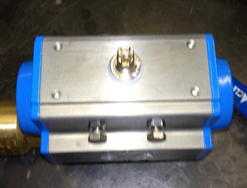
In this picture the pin in the center of the top of the pneumatic actuator can be used to drive accessories such as a valve position indicator. The four tapped holes allow a place to attach the bracket for the position indicator. The two bolts on the front in the lower half of the picture control the limits of rotation for the valve. These seldom require any adjustment since the actuator is set up with its valve in the factory.
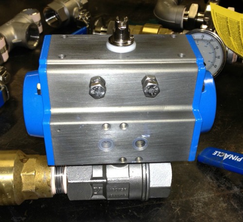
In the center of the picture you can see the two ports for the air connection. This is a single acting pneumatic actuator so one port is used to drive or turn the actuator, the same port is then used for exhaust when the air is turned off and the actuator spring pushes the valve back closed
If this were a double acting model, the physical appearance would be identical except that both ports would be used. One to open the valve and the other for exhaust. Then the reverse, the ports would be switched by a control valve so that the valve connected to the unit could be closed
The four tapped holes are used to attached control valves to the face of the actuator. This is more common when the actuator is installed in a pipe run.In situations such as pump skids the control valve is often located in a panel next to the PLC and other control equipment.
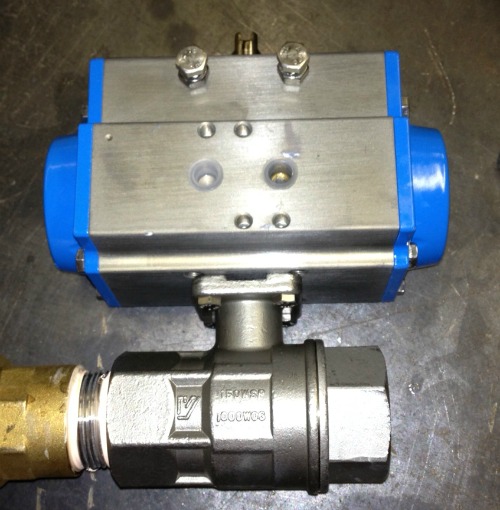
This particular unit was purchased complete with a one inch 316 stainless steel valve as a complete package. With small liquid valves, the actuators can bolt directly to the flange of the valve. With larger sizes it is necessary to put a bracket in between to create room a coupling to connect to the valve stem. The beauty of buying the the valve-actuator complete puts the onus on the supplier to deal with all the necessary brackets as well as the valve setup.
This valve-actuator is fine for use water but for solvents and hazardous liquids, you might need a different manufacturer if you have to provide TSSA certification. In Ontario, Canada there are seperate sets of regulations for the province of Ontario and for all Canadian provinces.
Aluminum Casting
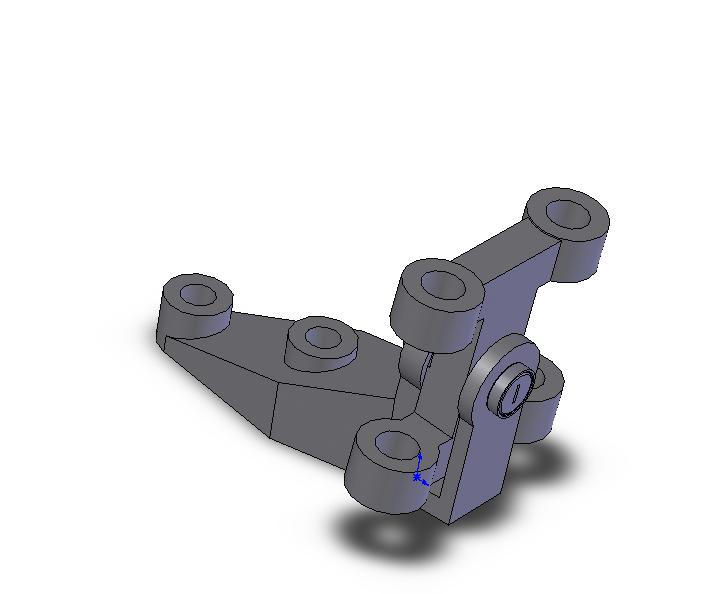
We can produce aluminum casting part drawings for both the permanent mould and die cast moulding processes. for the pump industry we produce casting drawings for pump volutes,impellers, motor mounts and more. In either case we can apply our experience to produce an casting part drawing that incorporates proper draft angles and appropriate machining allowances.
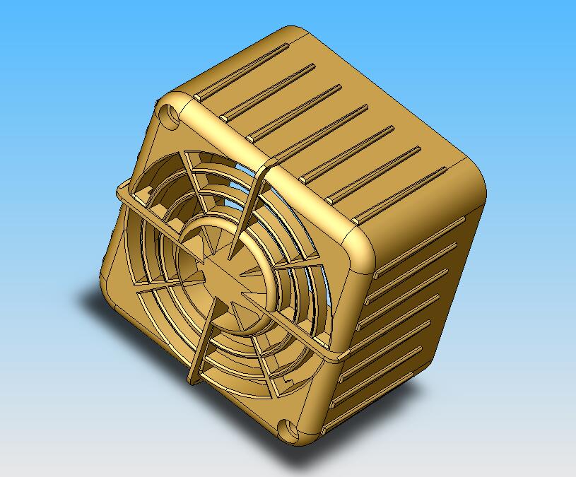
The permanent mould casting process is more suited to low volume production or prototype parts such as house numbers, medallions, novelty items and ornaments. We can use solidworks to create these parts and use the the software to predict the ultimate weight of the part to enable you to find the most economical part design.
We can address manufacturing difficulties before expenses are incurred in producing tooling. Aluminum die casting part drawings can be produced incorporating proper draft angles and allowances. We can take advantage of the ability of aluminum die casting to produce finely detailed parts at relatively low cost.
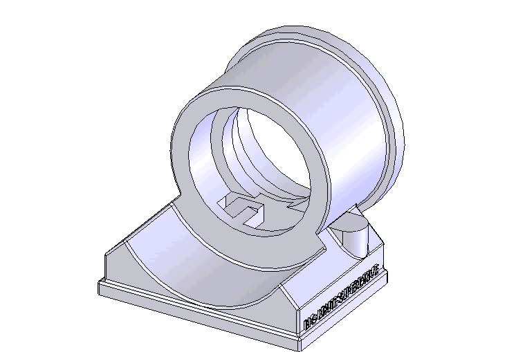
Casting drawings are also important if you are thinking of sourcing a part overseas and need to communicate the design intent with a supplier in the Far East or India.
If you have a new product and require aluminum alloy casting we can help you with its production. We deal closely with aluminum foundries and have sources for the manufacture of the part in addition to doing the design and drafting work for the aluminum alloy casting or aluminum die casting part drawings. Please contact us if you have any requirements.
Wax casting jewelry
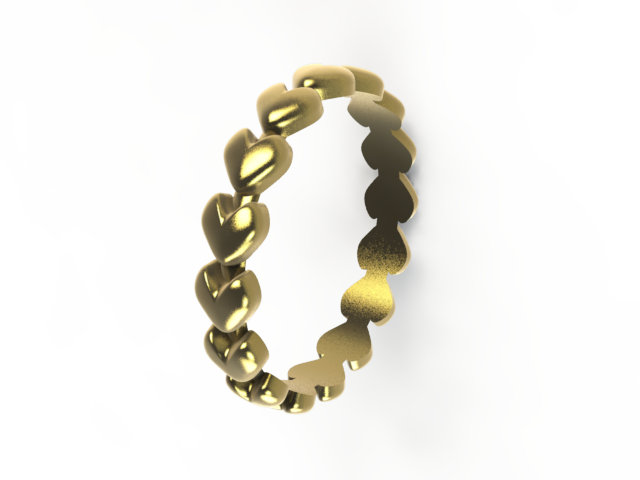
Custom jewelry making starts with wax casting jewelry models. The jeweler sculpts a special kind of modeling wax to create an exact replica of the piece of jewelry the customer is looking for. Most jewelers make this model painstakingly by hand but custom jewelry wax models can be made much more easily by using 3D modeling software.
Wax casting jewelry software makes changes easy and stores the models so they can be reused and modified quickly for new customers. The picture below shows a 3D model of a piece of jewelry created around singer Avril Lavigne's skull logo.
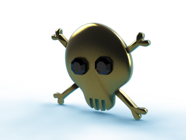
Models created on the computer can be saved to a file format called “STL”. The STL file is read by a machine called a wax printer, which creates a perfect wax model by spraying jets of wax, layer by layer similar to an ink jet printer. But the layers in a wax casting jewelry 3D printer are place one on top of the other, to create a finished part exactly like the model on the computer. Wax printers can create complicated wax models much faster than by hand. They can easily “print” engraving at the same time as they make the wax model.
Jewelry Casting Machine
Once the wax model is complete and approved, the jeweler places the wax model in a jewelry casting machine and fills the machines container with plaster. The plaster is allowed to harden around the wax model. An access hole is made so that molten metal can be poured in. Molten gold is then poured inside the plaster mold which immediately evaporates the wax model. This method is named “The Lost Wax process”.
The last step in wax casting jewelry is to spin the plaster mold with the molten gold inside at high speed so that centrifugal force makes all the gold fit into all the nooks and crannies in the mold. Part of the jewelers skill involves knowing how to make wax models that will cast easily. Complicated shapes may be possible on the computer, but the jewelers needs his experience to know what can be cast and what cannot.
Structural Steel Detailing
Structural steel detailing has a language all to itself. Most structural detailing is governed by common sense practices that have been proven out over decades of manufacturing and erecting steel supports and structures. There are guages to locate holes in angles, standard hole sizes, reccomended bolts and fasteners and all sorts of "rules of thumb" for locating and manufacturing gussets, plates and angles.
We use 3D modelling for steel structures especially where there is repetitive work, such as the four column support with angle bracing shown at the top right of this page. Entire sets of details can be generated by varying height, depth and width in the model. 2D Drafting is still used extensively because of the large amount of customer legacy drawing data still made in this format.
For structural projects related to residential homes and custom building in the United States we reccomend Opela Worx. This design firm specializes in the production of drawings and construction documents for building and for obtaining permits.
We work to CISC (Metric) and AISC (Feet-Inches) standards. Connections are as per the steel handbooks for both organizations including the use of 44W steel data to replace the old A36 standard.
OSHA ladders and handrails and process piping systems tend to go hand in hand with projects like structural supports, steel mezzanines and platforms, so there is a page we have devoted to osha compliant ladders and handrails and also piping drafting and design
The Manual of Steel Contruction link listed to the the bottom right is for "used" AISC handbooks, check here because there are often bargains. I paid full price on the
AISC website and if you can find one of these handbooks under $100, it's a good deal !
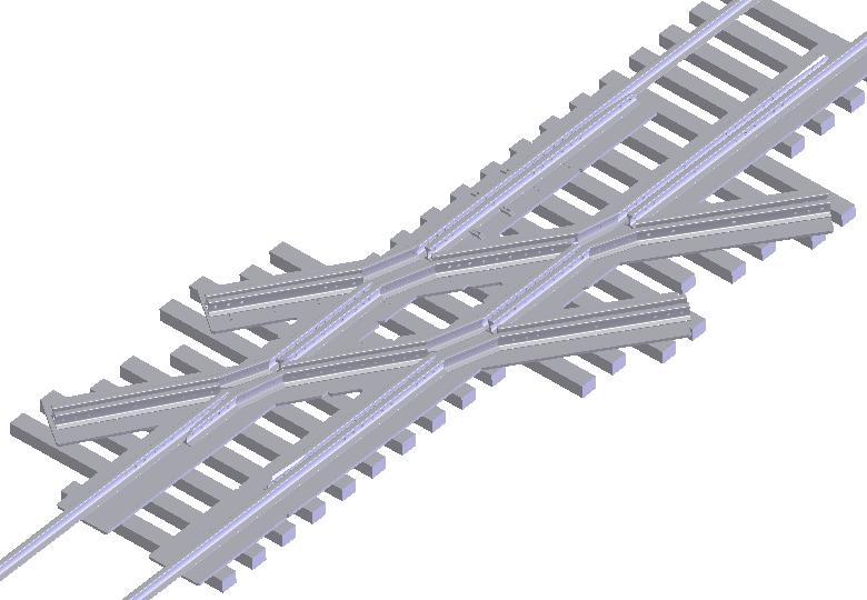
Diamond Crossing
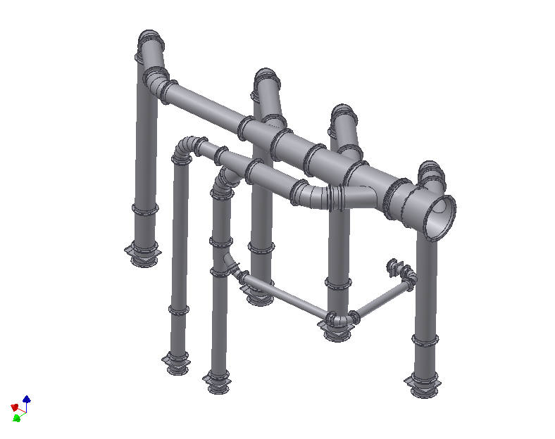
Duct Layout
